Example 단위값을 이용한 회로 해석

Example • Views 1668 • Comments 0 • Last Updated at 1 year ago  
  • 단위법의 개요
  • 단위값
  • 단위법

선 전압이 22.9[kV]인 3상 전원이 병렬로 연결된 2개의 부하에 공급되고 있다. (단위 값 변환시 3상 300[kVA], 22.9[kV]를 기준 값으로 한다.)

  • 부하1 : 300[kVA] (역률 0.8 지상)
  • 부하2 : 150[kVA] (역률 0.6 지상)
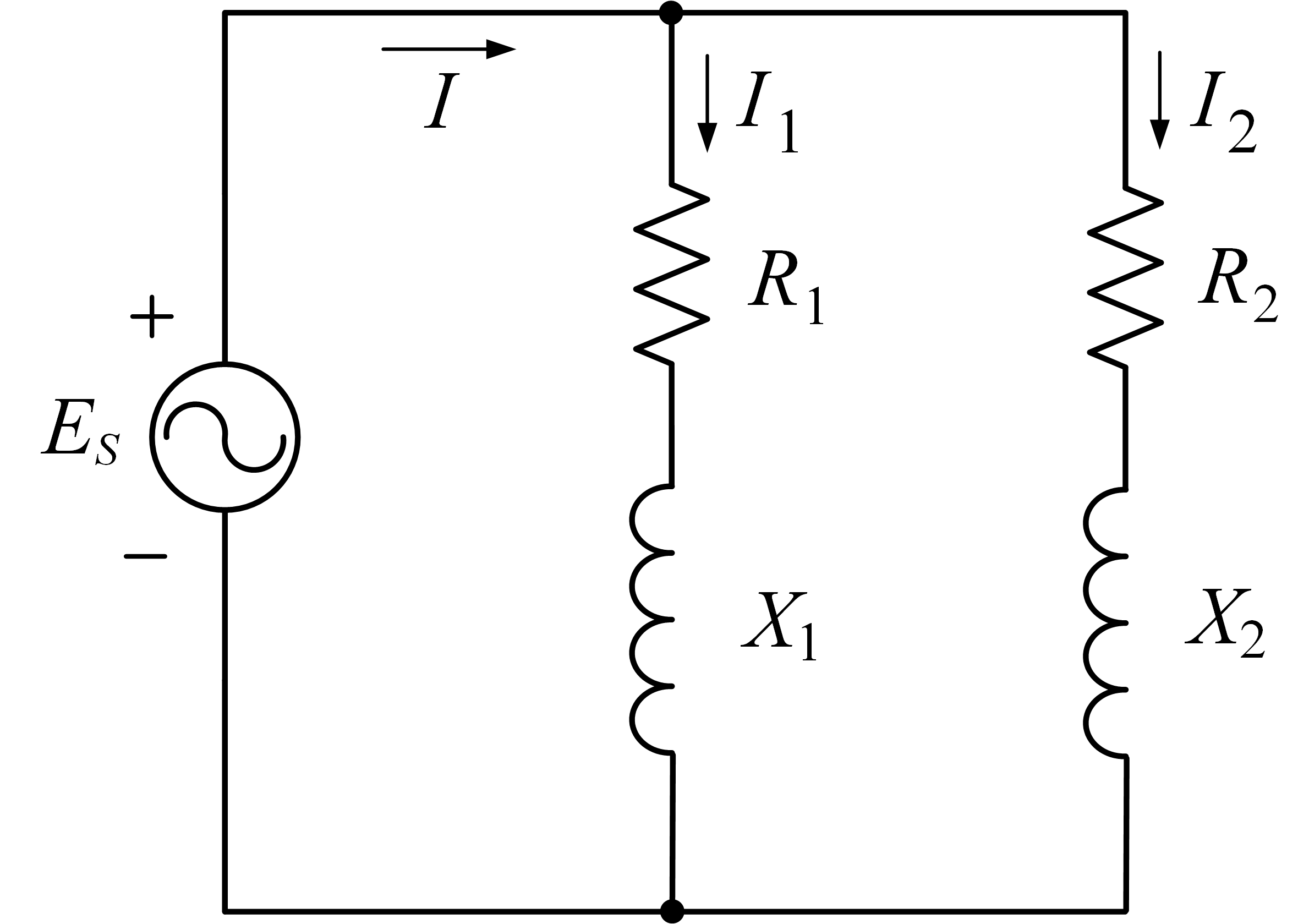
  1. 부하를 임피던스로 표현하고 회로도를 작성하여라.
  2. 부하 임피던스를 단위 값으로 변환하여라.
  3. 각 부하에 흐르는 실제 전류 값을 단위법을 이용하여 구하여라.

풀이

1. 부하를 임피던스로 표현하고 회로도를 작성하여라.

부하 1과 부하2의 임피던스 : Z1=R1+jX1\mathbf{Z}_ 1= R_1+ j X_1, Z2=R2+jX2\mathbf{Z}_ {2}= R_{2}+ j X_{2}, 각 부하가 소모하는 상당 복소 전력 : SL1\mathbf{S}_ {L 1}, SL2\mathbf{S}_ {L 2}이라고 하자. 상당 전원의 위상을 00으로 가정하면 다음과 같다.

ES=ES0=ES=22.9×1033=13.2[kV]\begin{align*} \mathbf{E}_ {S} &= E_S \phase{ 0} = E_S \\[2ex] &= \dfrac{22.9\times 10^{3}}{\sqrt 3} = 13.2 \, [\mathrm{kV}] \end{align*}

SL1\mathbf{S}_ {L 1}, SL2\mathbf{S}_ {L 2}은 다음과 같이 구할 수 있다.

SL1=SL13ϕ3(cosθ1+jsinθ1)=300×1033×(0.8+j0.6)=100×(0.8+j0.6)[kVA] \begin{align*} \mathbf{S}_ {L 1} &= {\dfrac{S_{L 1}^{3\phi}}{3}}\left(\cos\theta_{1}+ j\sin\theta_{1}\right) \\[2ex]&=\dfrac{300\times10^3}{3}\times(0.8 + j 0.6)\\[2ex] &= 100\times(0.8 + j 0.6)\,[\mathrm{kVA}] \end{align*}

SL2=SL23ϕ3(cosθ2+jsinθ2)=150×1033×(0.6+j0.8)=50×(0.6+j0.8)[kVA] \begin{align*} \mathbf{S}_ {L 2} &= {\dfrac{S_{L 2}^{3\phi}}{3}}\left(\cos\theta_{2}+ j\sin\theta_{2}\right)\\[2ex] &=\dfrac{150\times10^3}{3}\times(0.6 + j 0.8) \\[1ex] &= 50 \times(0.6 + j 0.8)\,[\mathrm{kVA}] \end{align*}

이로부터 각 부하의 임피던스는 다음과 같이 구할 수 있다.

Z1=[ES2SL1]=[(13.2×10³)2100×103×(0.8+j0.6)]=1.74×(0.8+j0.6)×103=1.39+j1.04[kΩ]=R1+jX1 \begin{align*} \mathbf{Z}_ {1} & = \left[{\dfrac{E_{S}^2}{\mathbf{S}_ {L 1}}}\right]^* = \left[\dfrac{(13.2\times 10^{3})^{2}}{100 \times 10^3 \times (0.8 + j 0.6)}\right]^* \\[3ex] &= 1.74\times(0.8 +j 0.6)\times 10^{3} \\[1ex] &=1.39 + j 1.04[\mathrm{k}\Omega] \\[1ex] &=R_1 + jX_1 \end{align*}

Z2=[ES2SL2]=[(13.2×10³)250×103 ⁣×(0.6+j0.8)]=3.48×(0.6+j0.8)×103=2.08+j2.78[kΩ]=R2+jX2 \begin{align*} \mathbf{Z}_ {2} &= \left[{\dfrac{E_{S}^2}{\mathbf{S}_ {L 2}}}\right]^* = \left[\dfrac{(13.2\times 10^{3})^{2}}{50 \times 10^3 \!\times(0.6 + j 0.8)}\right]^* \\[3ex] &= 3.48\times(0.6 +j 0.8)\times 10^{3} \\[1ex] & = 2.08 + j 2.78[\mathrm{k}\Omega] \\[1ex] &=R_2 + jX_2 \end{align*}

회로도는 다음과 같다.

2. 부하 임피던스를 단위 값으로 변환하여라.

먼저 부하 1의 부하 용량을 전력 기준 값으로 선정하고 선 전압을 전압의 기준 값으로 선정하고, 이로부터 상당 기준 값을 유도한다.

SB=SB3ϕ3=300×1033=100[kVA] S_{B}= {\dfrac{S_{B}^{3\phi}}{3}}=\dfrac{300\times 10^{3}}{3}= 100\,[\mathrm{kVA}]

VB=VBll3=22.9×1033=13.2[kV] V_{B}= {\dfrac{V_{B}^{ll}}{\sqrt{3}}} =\dfrac{22.9\times 10^{3}}{\sqrt{3}} = 13.2\,[\mathrm{kV}]

이로부터 부하 전력의 단위 값을 다음과 같이 구할 수 있다.

SL1,pu=SL1SB=0.8+j0.6[pu] \mathbf{S}_ {L 1,\mathrm{pu}}= {\dfrac{\mathbf{S}_ {L 1}}{S_B}} = 0.8 + j 0.6\,[\mathrm{pu}]

SL2,pu=SL2SB=0.3+j0.4[pu] \mathbf{S}_ {L 2,\mathrm{pu}}= {\dfrac{\mathbf{S}_ {L 2}}{S_B}} = 0.3 + j 0.4\,[\mathrm{pu}]

이로부터 부하 임피던스 기준 값을 다음과 같이 구할 수 있다.

ZB=VB2SB=(13.2×10³)2100×103=1.74[kΩ] Z_{B}= {\dfrac{V_{B}^2}{S_B}} =\dfrac{(13.2\times 10^{3})^2}{100\times 10^{3}}= 1.74\,[\mathrm{k}\Omega]

IB=SBVB=100×10313.2×103=7.57[A] I_{B}= {\dfrac{S_B}{V_B}} =\dfrac{100\times 10^{3}}{13.2\times 10^{3}}= 7.57\,[\mathrm{A}]

기준 값을 실제 값에 적용하여 다음과 같이 단위 값을 구한다.

Z1pu=Z1ZB=(1.39+j1.04)×1031.74×103=0.8+j0.6[p.u.] \begin{align*} \mathbf{Z}_ {1 \mathrm{pu}}= {\dfrac{\mathbf{Z}_ 1}{Z_B}} &=\dfrac{(1.39 + j 1.04)\times 10^{3}}{1.74\times 10^{3}} \\[3ex] &= 0.8 +j 0.6\,[\mathrm{p.u.}] \end{align*}

Z2pu=Z2ZB=(2.08+j2.78)×1031.74×103=1.2+j1.6[p.u.] \begin{align*} \mathbf{Z}_ {2 \mathrm{pu}}= {\dfrac{\mathbf{Z}_ 2}{Z_B}} &=\dfrac{(2.08 + j 2.78)\times 10^{3}}{1.74\times 10^{3}} \\[3ex] &= 1.2 +j 1.6\,[\mathrm{p.u.}] \end{align*}

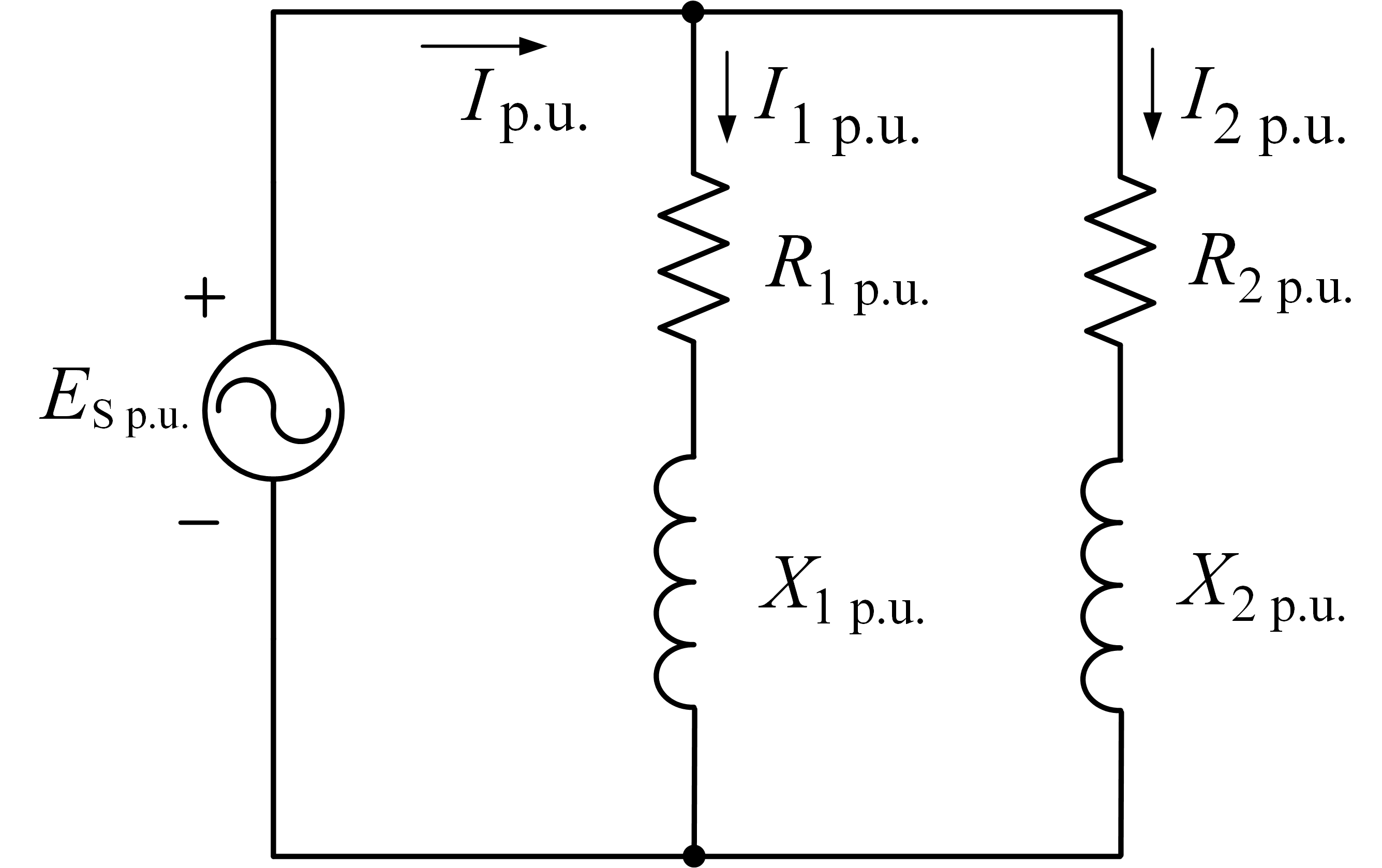
위의 결과로부터 아래와 같은 임피던스도를 구할 수 있다. 회로에서 각 요소의 값은 다음과 같다.

R1pu=0.8  ,  X1pu=0.6R2pu=1.2  ,  X2pu=1.6 \begin{align*} R_{1\mathrm{pu}}= 0.8 \;,\; X_{1\mathrm{pu}}= 0.6 \\[1ex] R_{2\mathrm{pu}}=1.2 \;,\; X_{2\mathrm{pu}}=1.6 \end{align*}

3. 각 부하에 흐르는 실제 전류 값을 단위법을 이용하여 구하여라.

회로도에서 각 부하에 흐르는 전류는 다음과 같이 구할 수 있다.

I1pu=[SL1,puES,pu]=[0.8+j0.61.0]=0.8j0.6=136.9[p.u.] \begin{align*} \mathbf{I}_ {1 \mathrm{pu}} &=\left[{\dfrac{\mathbf{S}_ {L 1,\mathrm{pu}}}{E_{S,\mathrm{pu}}}}\right]^* =\left[\dfrac{0.8 + j 0.6}{1.0}\right]^* \\[3ex] &= 0.8 - j 0.6 = 1\,\phase{ -36.9^{\circ}}\,[\mathrm{p.u.}] \end{align*}

I2pu=[SL2,puES,pu]=[0.3+j0.41.0]=0.3j0.4=0.553.1[p.u.] \begin{align*} \mathbf{I}_ {2 \mathrm{pu}} &=\left[{\dfrac{\mathbf{S}_ {L 2,\mathrm{pu}}}{E_{S,\mathrm{pu}}}}\right]^* =\left[\dfrac{0.3 + j 0.4}{1.0}\right]^* \\[3ex] &= 0.3 - j 0.4 = 0.5\,\phase{ -53.1^{\circ}}\,[\mathrm{p.u.}] \end{align*}

각 부하에 흐르는 전류의 실제 값은 다음과 같이 기준 값을 곱해줌으로써 구할 수 있다.

I1=I1puIB=(0.8j0.6)×7.57=7.5736.9[A] \begin{align*} \mathbf{I}_ {1} = \mathbf{I}_ {1 \mathrm{pu}}I_{B} &=(0.8 - j 0.6)\times 7.57 \\[1ex]&= 7.57\phase{ -36.9^{\circ}}\,[\mathrm{A}] \end{align*}

I2=I2puIB=(0.3j0.4)×7.57=3.7953.1[A] \begin{align*} \mathbf{I}_ {2}= \mathbf{I}_ {2 \mathrm{pu}}I_{B} &=(0.3 - j 0.4)\times 7.57 \\[1ex]& = 3.79\phase{ -53.1^{\circ}}\,[\mathrm{A}] \end{align*}

previous article
next article
Comments
Feel free to ask a question, answer or comment, etc.